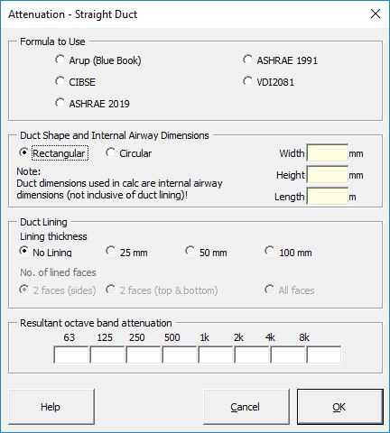

Strutt|Mechanical Services|Duct Elements|Straight inserts attenuation due to straight duct lengths into the active row of the worksheet. The attenuation in any octave band has been limited to 40 dB.
Attenuation for straight duct lengths can be calculated using the Arup Mechanical Services Guide, ASHRAE or CIBSE methods
The Arup Mechanical Services Guide (AIRAH) method is based on the AIRAH Duct Design Manual (1987) and calculates the attenuation in unlined straight ducts using the values from Table 12, which is attenuation, dB/m. Inputs required are the duct dimensions (either the internal (airway) dimensions or the external duct dimensions, depending on the user's preferences selected using Strutt Preferences) and the duct length.
The attenuation in lined straight ducts is calculated using the values in Table 13, which is attenuation in straight lined sheet metal ducts, absorption on two opposing faces, dB/m. Where absorption is on all 4 faces, the attenuation is calculated for both duct dimensions, and the total attenuation at each octave band is calculated as the square root of the sum of the squares of the attenuation values for each direction.
Note that the AIRAH/Blue Book method generally predicts lower losses than other methods (e.g. ASHRAE, CIBSE, Harris)
ASHRAE 1991 calculates the attenuation in unlined rectangular ducts using the equations:
For frequencies 63 - 250 Hz
`AT TN = 17 * (P/A)^-0.25 * f^-0.85 * L`; for P/A greater than 3
`AT TN = 1.64 * (P/A)^0.73 * f^-0.58 * L`; for P/A less than 3
Where:
`P` is the length of the duct perimeter (ft)
`A` is the duct cross-sectional area (ft2)
`f` is the 1/1 octave band centre frequency (Hz)
`L` is the duct length (ft)
At frequencies above 250 Hz:
`AT TN = 0.02 * (P/A)^0.8 * L`
The insertion loss of lined rectangular ducts is calculated by: `IL = B * (P/A)^C * t^D * L`
Where:
`P` and `L` are as defined above
`A` is the cross-sectional area of the free area inside the duct (ft2)
`t` is lining thickness (inches)
`B`, `C` and `D` are regression constants as defined in Table 5.4 ASHRAE.
The total attenuation is then calculated by adding the attenuation provided by an unlined rectangular duct to the insertion loss of a lined duct where:
`AT TN(T) = AT TN + IL`
The attenuation of unlined circular ducts is calculated using the data in Table 5.5 ASHRAE. Input required is the duct diameter and length.
The insertion loss of lined circular ducts is calculated by:
`IL = (A + B*t + C*t^2 + D*d + E*d^2 + F*d^3) * L`
Where:
`t` is the lining thickness (inches)
`d` is the inside duct diameter
`L` is duct length (ft)
`A`, `B`, `C`, `D`, `E` and `F` are regression coefficients given in Table 5.6 ASHRAE.
The sound attenuation provided by unlined circular ducts is negligible. Thus it is not included when calculating the total sound attenuation of lined circular ducts.
`AT TN = IL`
The CIBSE prediction method provides an empirical formula which appears to form the basis of the tabular ASHRAE (2011) guidance. Strutt calculates using the CIBSE formula because the ASHRAE 2011 guide only provides tabulated values.
For unlined rectangular or circular ductwork, Strutt uses the tabulated values in Table 5.4 of CIBSE Guide B
For lined rectangular ductwork, Strutt uses the following formula:
`IL=3.28 10^A (0.305 P_d/A_d)^B (0.039 t)^C`
where:
`A`,`B`,`C` are frequency-dependent coefficients
`P_d` is the duct perimeter (m)
`A_d` is the duct cross-sectional area (m2)
`t` is the lining thickness (mm)
Note: the above formula is valid for `P_d/A_d` ratios between 2 1/m and 30 1/m (0.6 1/ft to 9.1 1/ft).
Note: in the absence of 63Hz values in the CIBSE guide for the above methodology, we halve the 125Hz result. This is achieved by adding `-log10(2)` to the 125 Hz `A` coefficient.
For lined circular ductwork, Strutt uses the tabulated values in Table 5.5 of CIBSE Guide B
More information on the VDI2081 method can be found here.
The ASHRAE 2019 handbook provided an updated methodology for calculating the insertion losses for lined rectangular and circular ducts. The ASHRAE 2019 unlined duct insertion losses remain unchanged from the 2011 handbook.
The updated lined duct insertion losses are based on Research Project RP-1408. Empirical formulae were obtained for accurate interpolation between various duct lengths - these have been implemented in Strutt. For a full discussion of these formulae, the references are included at the end of this help page.
For unlined rectangular ductwork, Strutt uses the tabluated values in Table 16 of the ASHRAE 2019 handbook. Strutt interpolates the table based on `P_d / A_d`, where:
`P_d` is the duct perimeter (mm)
`A_d` is the duct cross-sectional area (mm2)
For lined rectangular ductwork, Strutt uses the following formula:
`IL=a_1 * (P_d/A_d)^2 + a_2 * (P_d/A_d) + a_3 + L * (b_1 * (P_d/A_d)^2 + b_2 * (P_d/A_d) + b_3)`
where:
`a_1`,`a_2`,`a_3`,`b_1`,`b_2`,`b_3` are regression coefficients for each frequency band. There is one set of coefficients for 25 mm lining and one set for 50 mm lining.
`P_d` is the duct perimeter (mm)
`A_d` is the duct cross-sectional area (mm2)
`L` is the duct length (m)
The total attenuation is then calculated by adding the attenuation provided by an unlined rectangular duct to the insertion loss of a lined duct where:
`AT TN(T) = AT TN + IL`
The empirical formula in ASHRAE 2019 is valid when the ratio `P_d/A_d` is between 0.083 and 0.278 1/in (0.0033 and 0.0109 1/mm) (for rectangular ducts) and when the duct diameters are between 12 in to 48 in (305 and 1220 mm) (for circular ducts).
A text box in the user form will warn the user if their cross-sectional dimensions are outside of the valid range.
The length range is 3 ft to 40 ft (915 mm to 12,190 mm) (for rectangular ducts) and 3 ft to 30 ft (915 mm to 9,145 mm) (for circular ducts)
For duct lengths outside of the ranges specified in the ASHRAE 2019 handbook:
For unlined circular ductwork, Strutt uses the tabluated values in Table 19 of the ASHRAE 2019 handbook.
For lined circular ductwork, Strutt uses the following formula:
`IL=a_1 * D^3 + a_2 * D^2 + a_3 * D + a_4 + L * (b_1 * D^3 + b_2 * D^2 + b_3 * D + b_4)`
where:
`a_1`,`a_2`,`a_3`, `a_4`,`b_1`,`b_2`,`b_3`, `b_4` are regression coefficients for each frequency band. There is one set of coefficients for 25 mm lining and one set for 50 mm lining.
`D` is the duct diamter (mm)
`L` is the duct length (m)
The total attenuation is then calculated by adding the attenuation provided by an unlined rectangular duct to the insertion loss of a lined duct where:
`AT TN(T) = AT TN + IL`
References: