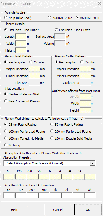

Strutt|Mechanical Services|Duct Elements|Plenum inserts the octave band attenuation from a plenum into the active row of the worksheet.

The Arup Mechanical Services Guide (Wells) method calculates attenuation from a plenum using:
Attenuation `= -10log_10 (S_2 (cos(theta)/(2 pi d^2) + 1/R_c))`
where,
`S_o` is the outlet area (m2)
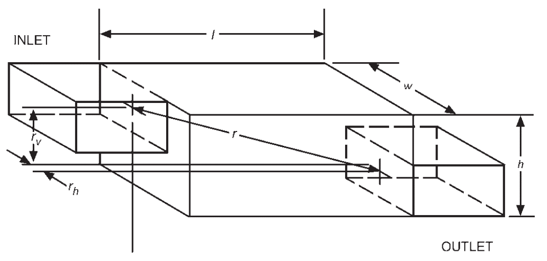
`d` is the slant distance inlet/outlet (m)
`theta` is the angle `d` makes with the inlet axis (deg)
`R_c` is the Room Constant and is derived from:
`R_c = (S_o + S_i + S bar(alpha))/(1 - bar(alpha))`
where,
`S` is the total internal surface area of the plenum (m2) excluding the inlet and outlet area
`S_i` is the plenum inlet area (mē)
`bar(alpha)` is the average absorption coefficient of the internal walls of the plenum excluding the openings
Strutt assumes that the inlet and outlet openings have `alpha = 1` and calculates the overall room constant accordingly

Inputs required in the calculation are:
Note: use both methods with caution where either the width or the height of the plenum is less than `1.5d`, in which case the plenum may not act as an expansion chamber
ASHRAE 2007 calculates attenuation from a plenum as follows:
Plane wave propagation in a duct exists at frequencies below the cutoff, creating the need to consider two frequency ranges. The cutoff frequency `f_(co)` is the frequency above which plane waves no longer propagate in the duct.
`f_(co) = c/(2a)`
or
`f_(co) = 0.586 c/d`
where,
`f_(co)` is the cutoff frequency (Hz)
`c` is the speed of sound in air (m/s)
`a` is the larger cross-sectional dimension of rectangular duct (m)
`d` is the diameter of a round duct (m)
Table 7 ASHRAE gives sound absorption coefficients for common plenum materials. These are incorporated into the calculation and the appropriate material can be chosen.
At the frequencies above fco, waves that propagate in the duct are called cross or spinning modes. The TL in this higher frequency range is predicted using:
`TL = b [(S_(out) Q)/(4 pi r^2) + (S_(out) (1 - alpha_a))/(S alpha_a)]^n`
`TL = b (K_f)^n`
where,
`TL` is the transmission loss (dB)
`b = 3.505`
`n = -0.359`
`K_f` is the attenuation coefficient
`S_(out)` is the area of plenum outlet (m2)
`S` is the total inside surface area of plenum minus inlet and outlet areas (m2)
`r` is the distance between centers of inlet and outlet of plenum (m)
`Q` is the directivity factor; taken as 2 for opening near centre of wall, 4 for opening near corner of plenum
`alpha_a` is the average absorption coefficient of plenum lining given by
`alpha_a = (S_1 alpha_1 + S_2 alpha_2)/(S_1 + S_2)`
where,
`alpha_1` is the sound absorption coefficient of any bare or unlined inside surfaces of plenum
`S_1` is the surface area of any bare or unlined inside surfaces of plenum (m2)
`alpha_2` is the sound absorption coefficient of acoustically lined inside surfaces of plenum
`S_2` is the surface area of acoustically lined inside surfaces of plenum (m2)
For lower frequencies below fco (with a limit of 50 Hz), TL is calculated as:
`TL = 10.76 * A_f S + W_e`
where,
`10.76` is a conversion factor from square metres to sqaure feet
`A_f` is the surface area coefficient (dB/ft2), referenced according to plenum size. NOTE: the coefficients in Table 13 in the SI version of the Handbook are incorrect - the coefficients from the IP Handbook are used instead, and the 10.76 correction factor is applied.
`W_e` is the wall effect (dB), selected by the user as the type of plenum wall lining
References: